
| Making a Altimeter with the Basic Stamp II | Introduction A method of determining altitude is by the use of barometric pressure; however, it is not done without difficulty. The relationship of pressure vs. altitude is not a linear one, it is actually a fairly complex one, which the army came up with in the 1930's. This is the equation for calculating altitude: Altitude = (10^(log(P/P_0)/5.2558797)-1)/-6.8755856*10^-6. Where P is the pressure at an unknown altitude, and P_0 is the pressure at sea level (zero feet). P and P_0 can be expressed in any unit because they are computed as a ratio. As you can see this is a fairly complex formula, but with a little bit of work and some math it is possible to compute with the Stamp. Figure 1 shows the non-linear relationship of pressure vs. altitude. As you can see on the graph as pressure decreases, altitude increases, but the higher the altitude gets the less pressure changes. In other words the higher the altitude gets the stepper the slope of the curve gets. That is what gives the curve its non-linearity. 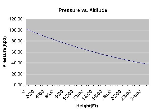 Figure 1 Since the Stamp will be calculating altitude and doesn't have log or floating point math capabilities a method know as linearization will be implemented in the Stamp code to get an accurate representation of the equation. The theory behind linearization it is that straight lines changing in slope at intervals along the curve can represent a non-linear curve. In other words, one non-linear equation can be represented by multiple linear ones that the Stamp is capable of computing. The Hardware The heart of the altimeter is the Motorola's MPX4115 pressure sensor. The sensor is temperature compensated from -40 to 125 C, this means that when fluctuation is temperature occur, it will not effect the sensors pressure reading. The sensor outputs an analog voltage proportional to pressure using this linear equation. Vout = 5 (P*0.009-0.095). The sensor also has on-chip signal conditioning to produce an output range of 0.2V at (15Kpa) to 4.8V at (115Kpa). The signal conditioning makes the output much easier to work with. However, the analog-to-digital converter (ADC) I'm using only has a maximum input voltage of 4.096V, so additional signal conditioning will have to be implemented. All of these features make the MPX4115 pressure sensor ideal for altimeter applications. The one channel, 12 bit, serial peripheral interface (SPI) ADC from MAXIM Integrated Products (www.maxim-ic.com) will be used to read the output voltage of the op-amp. The MAX187 has internal 4.096V voltage reference (REF) as well as an option to use an external reference. The voltage reference determines the full scale input of the ADC, which in this case its 4.096volts. I chose to use the internal reference because it will give you a better resolution and makes it easier to calculate the voltage. The ADC's resolution is determined by the following equation: Resolution = voltage Ref/Counts. The number of counts the ADC has is determined by how many bits it is. Eight bit ADC's have 256 counts and a 12 bit ADC has 4096 counts. So as you can see by using the internal voltage reference it makes it much easier because each count is equal to 1mV. The MAX407 from Maxim provides a dual op-amp that will suit the bill for this project. The MAX407 operates on a single +5V supply and requires less then 1.2uA per amplifier, which is a good for battery operated projects where current draw should be kept to a minimum. Figure 2 shows the complete schematic diagram of the altimeter circuit. 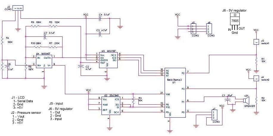 Figure 2 The op-amp circuit is a very crucial part in getting good accuracy and resolution out of the altimeter. The op-amp portion of the circuit will serve two purposes; one is to increase resolution. The second is to reduce the maximum output voltage of the pressure sensor so it doesn't exceed the full-scale input of the ADC. 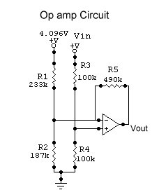 Figure 3 Figure 3 is the schematic diagram of the op-amp portion of the circuit. The voltage that the ADC reads is the output of the op-amp. However, to determine pressure the voltage into the op-amp must be known. This can be calculated using the following equation: Rp = R1*R2/(R1+R2) Vout = Vin* R4/(R3+R4)*(1+R5/Rp) - 4.096 * R2/(R2+R1) * R5/Rp The resistor values used in the opamp circuit are then plugged into the above equation then similfied and rearranged to solve for Vin. Vin =(Vout/2.86) + 3.01 Now that the voltage output of the pressure sensor is known, the pressure applied on it can be calculated using this equation found in the MPX4115 data sheet. P = ((Vin/5)+0.095)/0.009 To make things a bit simpler both equations can be combined into one. P = (((Vout/2.86)+3.01)/5+0.095)/0.009 Now we got the equation for calculating pressure with the voltage applied to the ADC's analog input. The next step is to convert the equation to stamp math so the Stamp can calculate the pressure applied on the sensor P(in 100xKpa) = Vout*/1991/10+7744 So as you can see the resistor values used in the op-amp circuit determine equation for calculating pressure, but they also determine the altitude range of altimeter. I chose a range of 0-7000 feet and chose my resistor values accordingly. Assuming the pressure sensor's output varies from 0 to 4.096V over the range of 0-7000feet we would get a resolution of about 1 foot. Unfortunately, this isn't the case. The sensor outputs ~4.2V at 0 feet and ~3V at 7000feet. With no signal conditioning only the upper quarter of the ADC range is used, thus decreasing the altimeters resolution drastically. Here is how the resolution of the altimeter is calculated. Resolution = ADC count range/pressure range Without the op-amp circuit the resolution would work out to be approximately 6feet, (1200/(103-78kpa)) = 48 counts/1Kpa. With the op-amp circuit the resolution goes down to approximately 2 feet (3400/(103-78))= 136 counts/1Kpa. So as you can see the op-amp circuit nearly triples the resolution of the altimeter. Calculating the pressure was the easy part, the hard part is using the pressure to determine the altitude. As I mention earlier the relationship of pressure vs altitude isnt a linear one, logs and anti logs are required to calculate altitude. Since the stamp isnt capable of doing logs a method know as linearization will be implemented to overcome this problem. 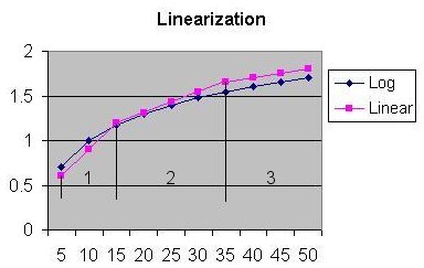 Figure 4 Figure 4 shows how linearization works. The blue line is a graph of a logirytmic equation and the pink line is an example of how 3 linear lines can closely reproduce a logirythmic equation which is know as linearization. However, there are a few draw backs to the linearization method. One is that alot more code and mathimatical calculations are needed to implement it. Although linearization is much better then using just one linear equation for determining altitude, it does have some error. Using the linearization method will result in approximately +/-2.5% error in the altitude calculation. Pictures Click on image to inlarge. 
  Downloads Parts Needed
Functions Coming soon... Conclusion 
I got to test my altimeter out this summer(Aug 30/99) as i hiked up Mt Kathdin in Maine. At the top i got a reading of 5180 feet, which is really good considering i was only using the linear eqation. Mount Kathdin is 5267 feet, so i was only a little bit out . Above is a graph of time vs Altitude of hiking the mountian, and a picture of my Altimeter near the top of Mt Kathdin. Here is a picture of my old altimeter near the top of the mountain.  |
