
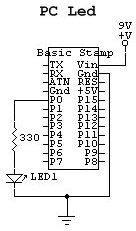
| Building a Basic Stamp II Relay controller using Visual Basic 5. | Introduction This project will show you how to build relay controller using a Stamp connected to a PC serial port. The PC, using Visual Basic 5 controls the Stamp though a serial interface and the Stamp controls the Relay from one of it I/O pins. This is a screen shot of the Visual Basic 5 Program i made to control a Relay. The program is pretty straight forward, select your com port, then hit connect. Then you just hit on or off to turn the relay on or off, the state of the connection is also showed at the bottom. I will make this software available to anyone who wants it, feel free to modify it and way you wish. 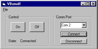 The best way to test if your PC is communicating with your Basic Stamp, without building the relay circuit, is to build this LED circuit showen below. Program your Basic Stamp with vbonoff.bS2, then run the visual basic software and connect the stamp to a Comm port. Now connect up the Led circuit as showen it the schematic. Then with the Visual Basic 5 program running select the comm port your using and press connect. Now the led should turn on and off as you hit the button. Schematic for LED circuit Relay Schematic Now that you know everything is working correctly you can build the relay circuit. The transistor used are NPN type, i used a 2N2222, but any NPN transistor will do if you dont have any 2N2222 around. The relay is a general purpose 5V relay, but any relay could be used as long as its 5V relay. The five volts is what voltage is needed to turn on the coil, most relays can take 120VAC at the contacts. The purpose of the diode across the relays coil is to protect the NPN transistor from back emf voltage spikes when the relays is turn off creates. A 1N4001 diode will do fine, but if you can use higher values such as 1N4005 too. Note: Be sure not to use the stamps voltage regualtor for powering up the relay coil becuase it can only source 50mA, and one relay would use close to 60mA. 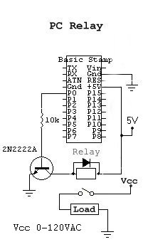 Downloads Note: The Visual Basic code is the code you can edit in Visual Basic 5, the Visual Basic program is a setup file to install vbonoff.exe. If you dont have Visual Basic 5 you can install this and and still control the relay circuit. Formula's Here is some formula's for calculating the voltages and currents for the relay circuit. Vbe= 0.7V - the voltage across the base and the emitter of the transistor is aways assume to be 0.7V Ib=(Vbb-Vbe)/Rb - Vbb is the eather 5(high) or 0V's(low). Rb is the resistor at the base(10 Kohms) Ic=Beta*Ib - beta is the gain of the transistor different for each transistor(usually around 150). Ie=Ic+Ib - Ic is the current going through the relay's coil. Vce= Vcc-Ic*Rc - Rc is the relays coil resistance. The current sourced to the base of the transistor from the I/O pin is only around .43mA. So you could use up to 16 relays with no problem. Conclusion By using this project as a starting point you can design your own relay controller with a bigger capacity. You could even building one to control sixteen relays with the Basic Stamp II using this project as a example. Most relays can can take 120 VAC at there contacts so the limits are endless what you could turn on with relays. This is a very simple project to build and program but very powerful. |

Questions or comments email me at
Shaunwilson19@yahoo.com
ICQ# - 11278365