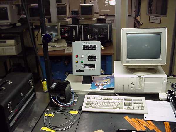
Drive Information
Drive functions include absolute and incremental moves, clockwise (CW) and
counter-clockwise (CCW) jogging in both a high and low speed, a home
function with limit switch, making X number of steps at F velocity,
reading complex data instructions through thumbwheels, PLC communication and
several others.
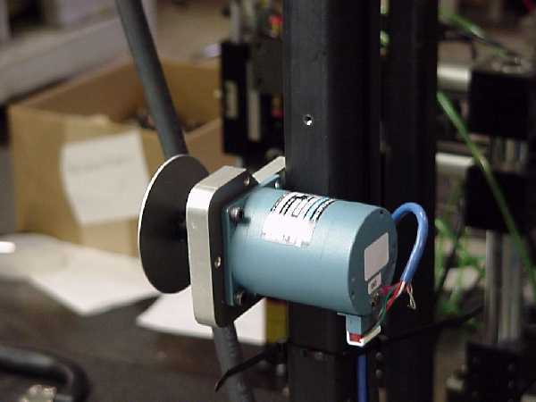
It can drive its stepper motor in a number of modes: supplying power to the motor at all times when a holding torque at stand-still is needed; supplying power to the motor only when in motion (all windings off) when no torque is needed at stop or when motor heating is a concern; increasing the current during motion to increase acceleration and torque; or, with reduced current for better efficiency when full power is not necessary. In a free standing, no load demonstration application, these modes will have little effect on motor performance except for motor temperature.
Like most motor drives, the 3180 EPI produces lethal voltages. Care must be taken to avoid contact with motor or drive while power is supplied, and proper grounding procedures must be used. The drive contains a number of capacitors which store dangerous voltages after the drive has been turned off. Wait five minutes after shutting off power before making any connection changes or handling the drive.
RS-232 Connections
The 3180 EPI drive is not programmed so much as it is wired.
Although the 3180 EPI drive can be further programmed with additional
information and parameters, most commands can be given through switches
and thumbwheels. In fact, this drive can be operated right
out of the box without ever being connected to a computer.
The drive is connected to the controlling switches and thumbwheels by a 25 pin parallel connection located next to the 9 pin port. (See Appendix) This includes 7 outputs for PLC communication, 8 inputs and 8 outputs for switch and thumbwheel connections (which includes 2-4 programmable inputs).&nBy connecting the 8 outputs (or Strobe 0-7) to the 8 inputs (or Data 0-7) in various combinations, the drive can be run, given data and even programmed.&nStrobes 2-7 are dedicated to be used with thumbwheels for data collection.&nStrobes 0 and 1 are used for limit switches, cycle start and stop switches, jog control, programmable inputs, data-load and other drive controls.
During normal operation, only Strobe 0 and Strobe 1 are activated - the data fields are ignored and any changes to the thumbwheels or selector switches will be ignored. When the Load switch is actuated (Strobe 1 is connected to Data 2), Strobes 0 & 1 are deactivated and Strobes 2-7 are activated. The data from the thumbwheels is read and processed. Strobes 0 & 1 are re-activated and Strobes 2-7 are turned off again.
Information is taken from the thumbwheels in Binary Coded Decimal (BCD) format. Pin connections are assigned values 1, 2, 4, 8, 10, 20, 40, 80 through 80,000,000.
For example, if Strobe 7 were connected to Data 1, 2 & 7, Strobe 6 were connected to Data 0 & 3, and Strobes 4 & 5 were connected to no Data pins, the drive would read a value of 986. (see appendix). These connections are made inside the thumbwheel hardware. Example #2, if the ones digit read 6, it would connect Strobe 7 to Data 1 & 2.
There are two sets of data fields: Strobes 4-7 can read values from 0 to 99,999,999, which is recorded and a numeric value - for example, the number of steps to be taken; Strobes 3 & 4 can read values from 0 to 999 which activate commands, line numbers in a program, or set parameters and speeds.
The meaning of the data fields is determined by the selector toggle switches
connected to Strobe 4 and Data 5-7. Eight combinations are
possible (2^2) which allows the code Strobes (3&4) and the value Data
(5-7) to be read as:
0 Line Number to be executed 4 L Command which sets parametersMany G Commands, H commands and Strobe 0 & 1 commands are redundant. For further information about L, G, H commands and default settings, see Appendix in Superior Drive Manual.
1 G Command to be executed 5 H command to be executed
2 Distance or number of steps 6 Return to default settings
3 Velocity 7 not used
By wiring the drive to one or two thumbwheels and an number of switches or relay contacts, the drive can be run, jogged, programmed and adjusted to meet changes in application. Not all pins need be wired. This drive was originally set up to be run with only one thumbwheel for data values and a few switches.
Applications
An open loop stepper motor can be used in a great number of applications and
has the advantage of being cheaper than a full servo system.
Their best use is in simple intermittent motion or when precise steps
are needed. Such applications may be advancing a printer one
line at a time, twisting a wire a determined number of turns, some
intermittent motion conveyor applications, laser or pen positioning and
table movement.
The Strobe and Data pins can be connected in variety of ways, suited to each application. The easiest way to enter numeric data is either through thumbwheels or through a computer terminal. The remainder of the connections could be controlled by push-buttons, selector switches, toggle switches, limit switches, relay contacts (which could be energized by a PLC or hard-wired logic) or a combination of these.&nThe Cycle Start command could be wired to a push-button switch that an operator would activate as well as a set of relay contacts which may be energized by a PLC.&nSome other connections may not be used at all, depending on the application.
Appendix
				   Strobe 0                Strobe 1
Pin#          Assignment
1       Signal Common Vo       Data 0 CW Limit               CW Jog
2       Data 7 Input           Data 1 CCW Limit             CCW Jog
3       Data 5 Input           Data 2 Home Limit           Data Load
4       Data 3 Input           Data 3 Clear Cycle     All Windings Off
5       Data 1 Input           Data 4 Pause            High/Low Speed
6       Motion Busy Output     Data 5 Input #1           Enable Jog
7       Strobe 7 Output        Data 6 Input #2            Cycle Start
8       Strobe 5 Output        Data 7 Stop Cycle       9/25 Pin Connection
9       Strobe 3 Output
10      Strobe 1 Output
11      Output #2
12      All Windings Off Output
13      CW/CCW Output
14      Signal Common Vo
15      Data 6 Input
16      Data 4 Input
17      Data 2 Input
18      Data 0 Input
19      Position Error Output
20      Strobe 6 Output
21      Strobe 4 Output
22      Strobe 2 Output
23      Strobe 0 Output
24      Output #1
25      Pulse Output

	Strobe2   Strobe3      Strobe4   Strobe5   Strobe6   Strobe7
Data 0      1       100           1M      10k       100         1

Data 1      2       200           2M      20k       200         2

Data 2      4       400           4M      40k       400         4

Data 3      8       800           8M      80k       800         8

Data 4     10       +/-          10M     100k        1k        10

Data 5     20      Sel 1         20M     200k        2k        20

Data 6     40      Sel 2         40M     400k        4k        40

Data 7     80      Sel 4         80M     800k        8k        80
	      Code Data                 Value Data

Example:
Connecting Strobe 7 to Data 1, 2 & 7 yields 2 + 4 + 80 = 86
Connecting Strobe 6 to Data 0 & 3 yields 100 + 800 = 900
Connecting Strobes 4 & 5 to no Data pins yields 0
			86 + 900 + 0 =986

Example:
Connecting Strobe 2 to Data 0, 3, 4, 5 yields 1 + 8 + 10 + 20 = 39
Connecting Strobe 3 to Data 5 & 7 yields (Sel 1) + (Sel 4) = Select 5 = H code
H Code 39 Enables Reduce Current Mode

By setting the Data Value Thumbwheel to 986, the Code Data Value to 39 and
the Selector Toggle switches Up, Down, Up these connections are made within
the hardware.
__
For more complex sequences, the drive can be programmed with Slo-Syn DOS
based software through a RS-323 communication cable.
The information provided both in the software help files and the drive
manuals for the computer connections is incorrect. The
proper connection for 9-pin to 9-pin communication is to connect pins 2
to 2, 3 to 3, 5 to 5 (or Tx to Tx, Rx to Rx & Vo to Vo).
For further information, consult manual pg 5-1 through 5-22
--
Evan Garrett
Paul Adleman
March 20, 2000
2nd year APKG